
Model and Specification of Magnetostrictive Displacement Sensor
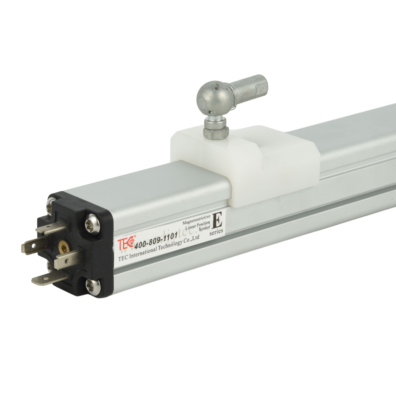
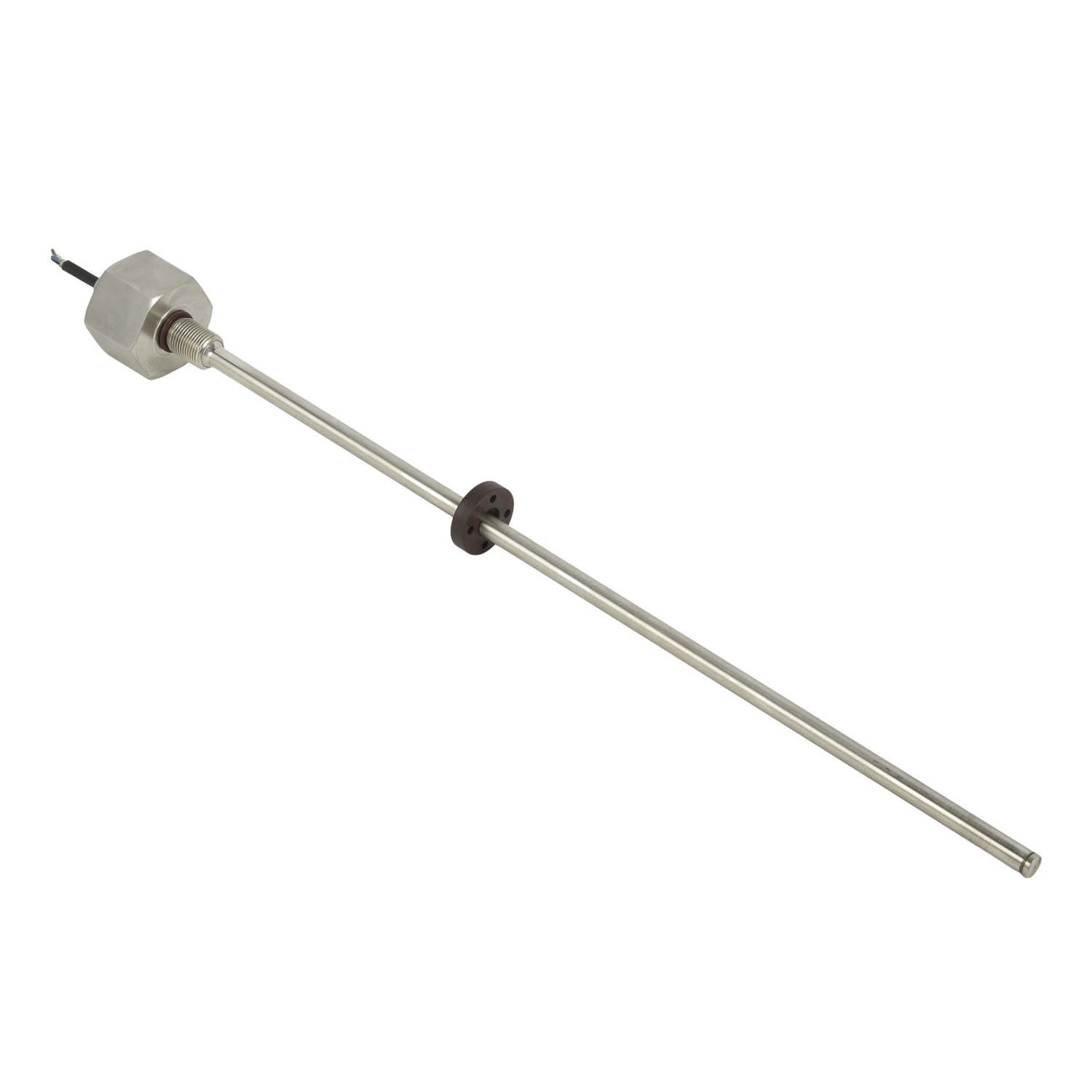
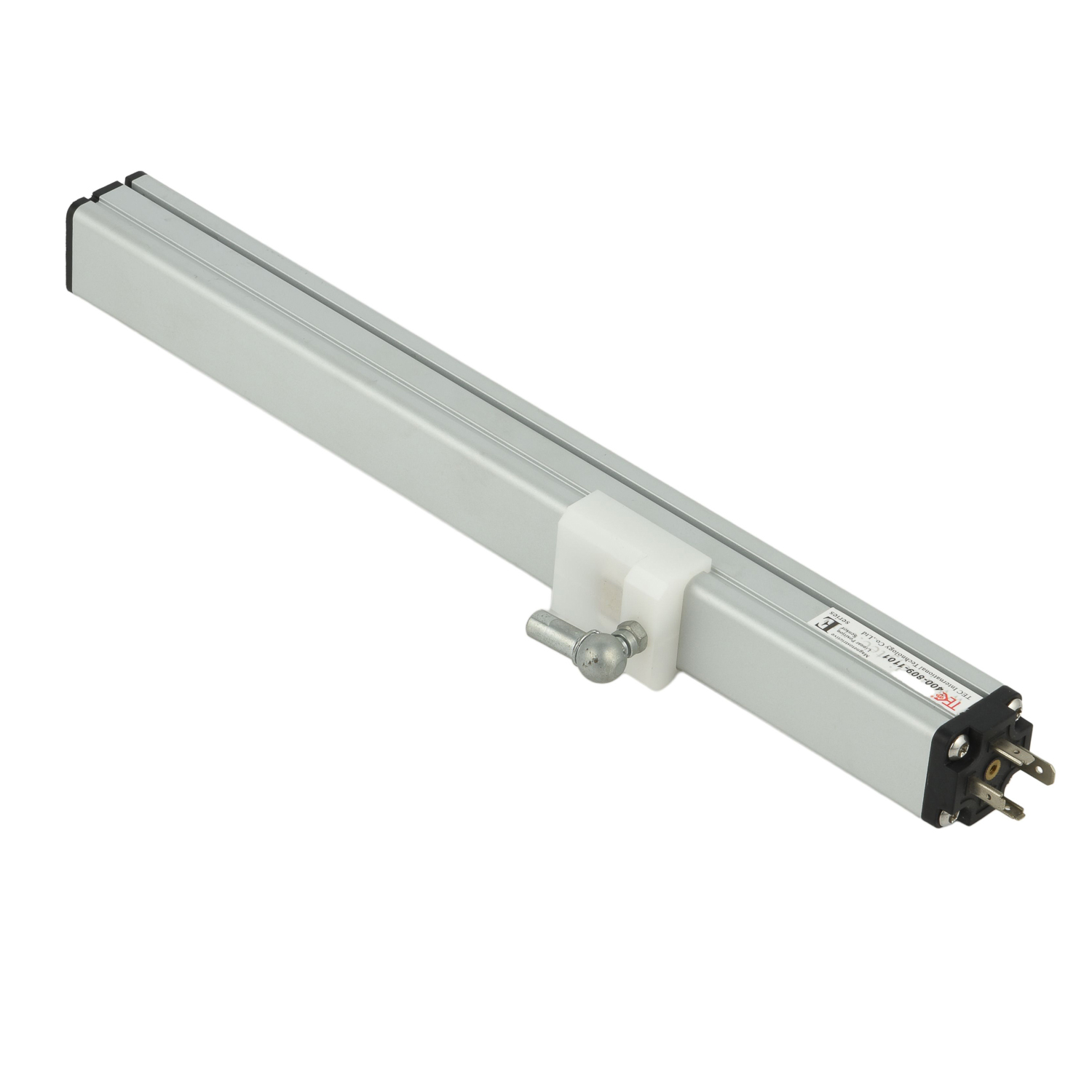
Magnetostrictive displacement sensors use the Wiedemann effect and ultrasonic time-of-flight to measure linear position with high accuracy and durability. A typical model number encodes stroke length, output signal, supply voltage, thread size, and rod material. For example, MS-500-A0-V1-M18 means a 500 mm stroke, analog 0–10 V output, 24 VDC supply, M18 thread, and standard stainless-steel rod. Specifications usually include measuring range from 50 mm to 5000 mm, nonlinearity ≤0.05% FS, repeatability ≤0.002% FS, resolution up to 1 µm, and hysteresis ≤0.01% FS. Output options include 4–20 mA, 0–10 V, RS485, CANopen, SSI, and EtherCAT. Supply voltage is often 24 VDC (12–30 V), with protection against reverse polarity, surge, and short circuits. Operating temperature may range from -40°C to +85°C, while IP67 or IP68 protection suits harsh environments. The sensor consists of a waveguide, movable magnet, damping element, and electronics head. It provides absolute position without re-zeroing after power loss. Important specs also cover shock/vibration resistance, pressure rating for hydraulic cylinders, and cable/connector type. When selecting a model, match stroke, output, mounting thread, and environmental rating to the application. Magnetostrictive sensors are widely used in injection molding, hydraulic presses, steel mills, energy equipment, and automation lines. Correct model and specification ensure long life, stable feedback, and precise motion control.
 Field Application of Magnetost
Model and Specification of Mag
Import Substitute Magnetostric
Field Application of Magnetost
Model and Specification of Mag
Import Substitute Magnetostric
 Installation Method of Magneto