
Installation Method of Linear Displacement Sensor
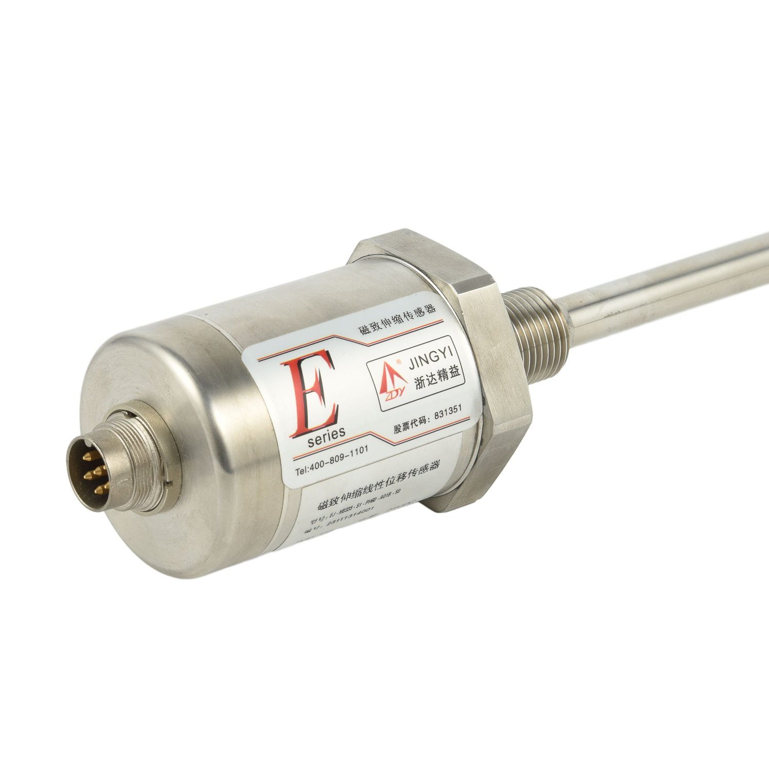
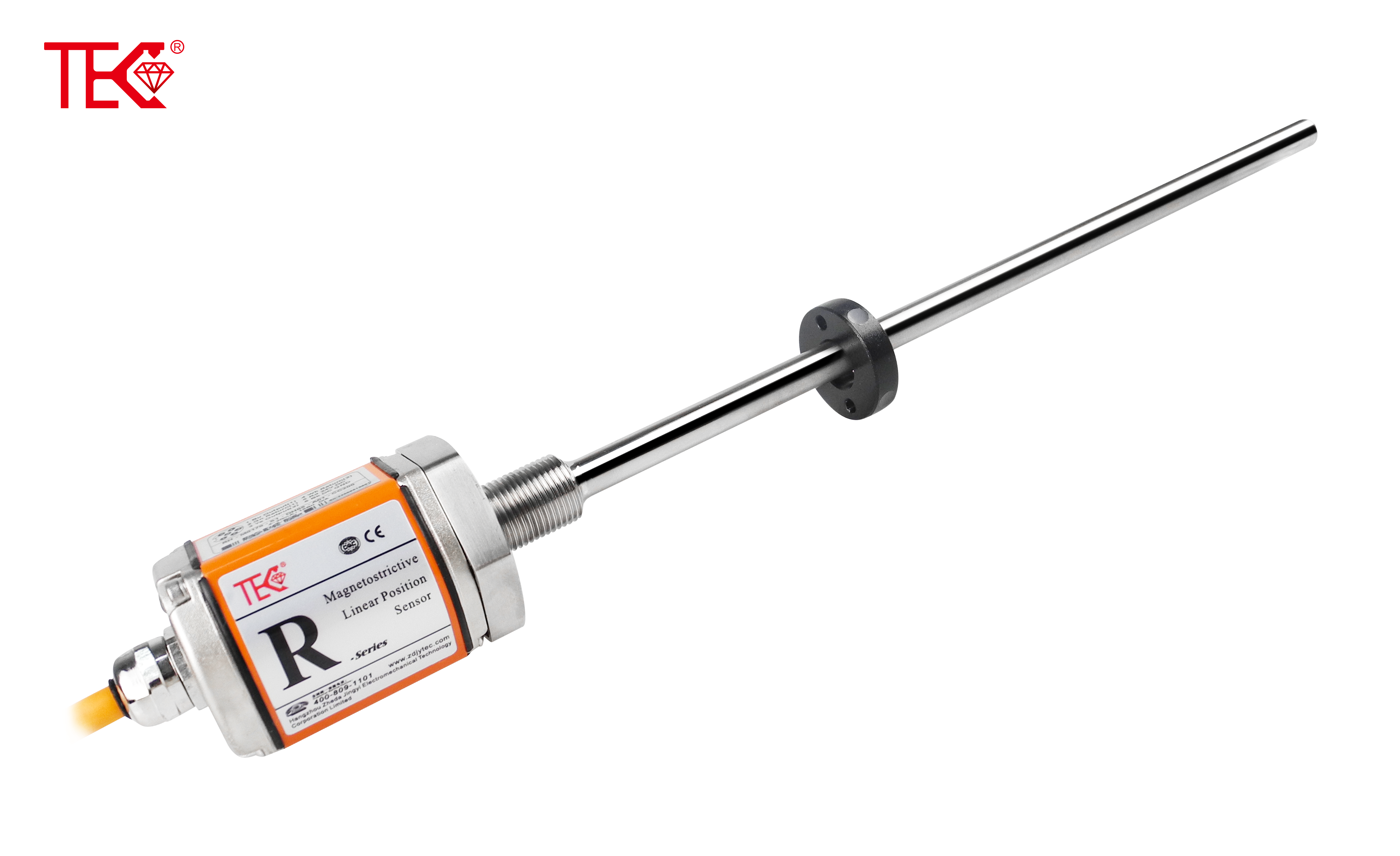
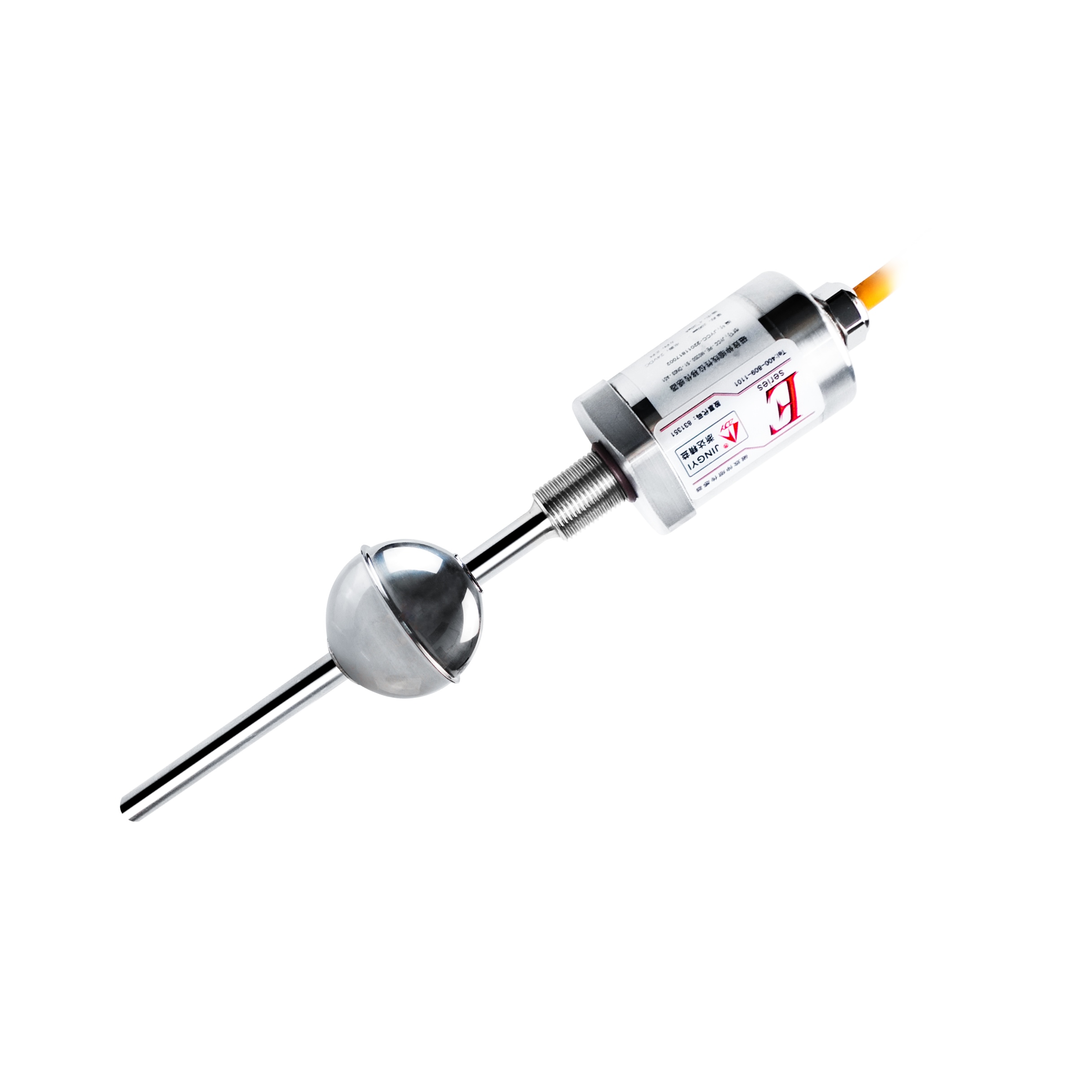
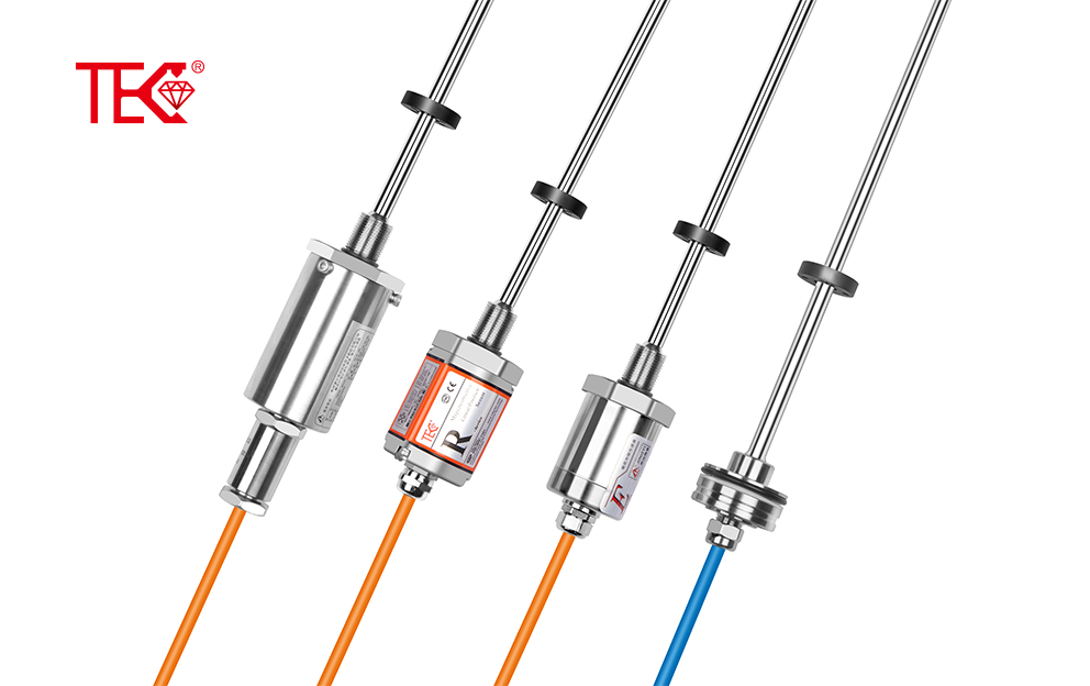
Installing a linear displacement sensor correctly ensures accurate, repeatable measurement. Choose a rigid, vibration-resistant mounting surface. Mount with threads, flanges, or brackets without over-tightening; excess stress can distort the coil or core. Align the sensor with the motion axis. Keep the stroke centered and avoid bottoming out. Angular or parallel misalignment causes side loading, friction, and signal error. For LVDT or magnetostrictive types, keep the core or magnet centered within the rated stroke. A flexible coupling or spherical rod end can absorb small misalignments. Never use the sensor rod as a mechanical guide; it must move freely without bending.
Set zero. Move the target to the range start and confirm minimum output; then check maximum at full scale. Tighten gradually and recheck alignment. Check readings after final tightening, because clamps can shift the core. Support long-stroke rods to prevent sag.
Route cables away from motors, drives, and high-voltage lines. Separate signal cables from power cables to reduce electrical interference. Use shielded cable, grounding the shield at one end to avoid loops. Follow the wiring diagram for excitation, signal, and common wires. Use a stable supply and protect against voltage spikes. Add filtering if noise appears.
Protect from dust, coolant, oil, and impact with bellows, covers, or IP-rated housings. Calibrate over the full stroke and record output. Document the zero and span settings for future maintenance. Check mounting, couplings, and cables regularly. Proper mounting, alignment, wiring, and protection ensure reliable long-term performance.
 Import Substitute Linear Displ
Installation Method of Linear
Import Substitute Linear Displ
Installation Method of Linear
 Working Principle of Linear Di
 Technical Parameters of Linear