
Metallurgy Hydraulic Cylinder Built-in Linear Displacement Sensor Selection
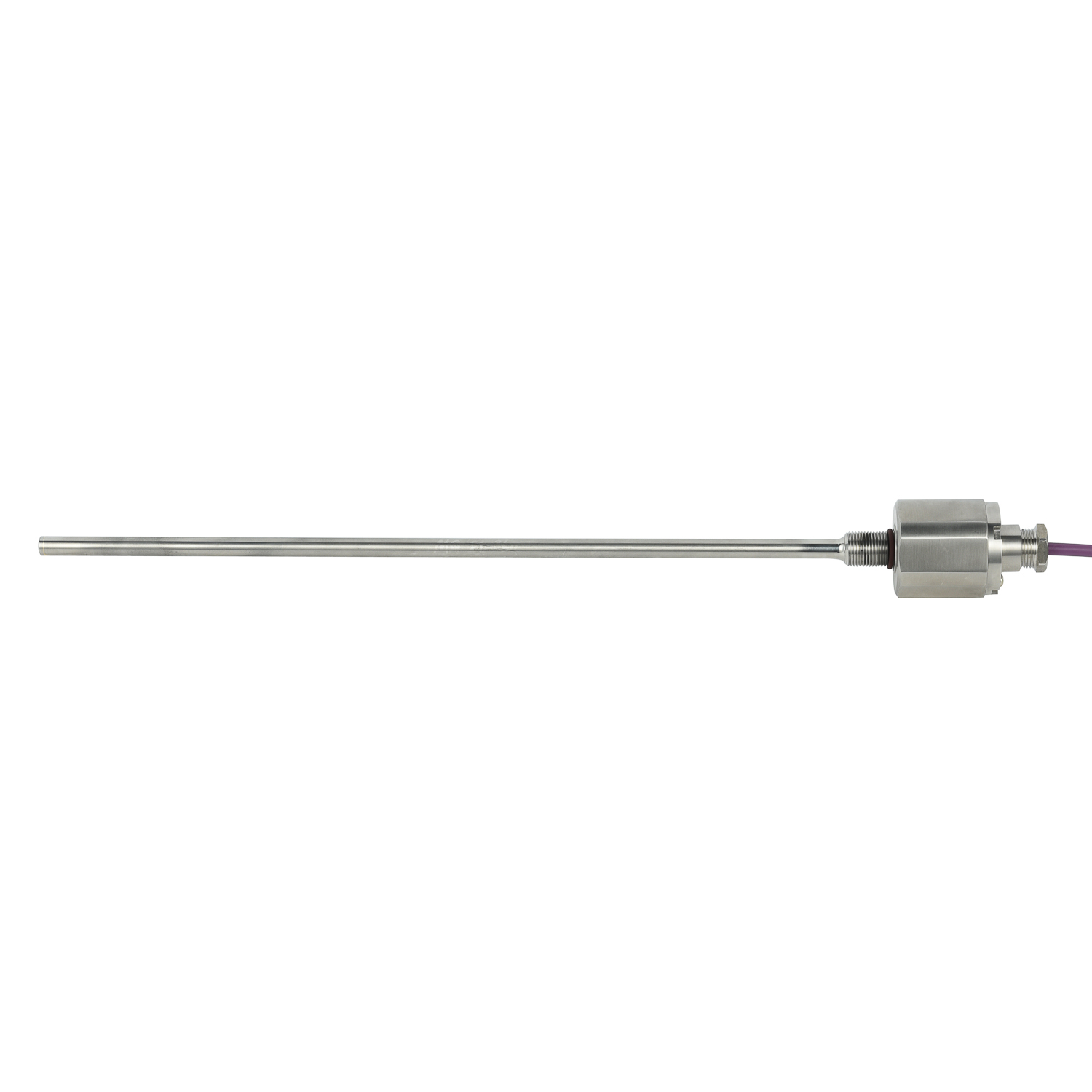
Selecting a built-in linear displacement sensor for a metallurgy hydraulic cylinder is a reliability decision, not only a measurement choice. The sensor must survive high temperature, steam, dust, shock, vibration, pressure peaks, and electromagnetic interference while delivering stable position feedback for closed-loop control.
First define the hydraulic stroke, required resolution, repeatability, and update rate. Choose a measuring range with safe mechanical margins, and confirm that the sensor fits the cylinder bore, rod drilling, and mounting space. Pressure resistance, sealing, and rod material compatibility are critical because the sensor is exposed to hydraulic oil and aggressive cleaning.
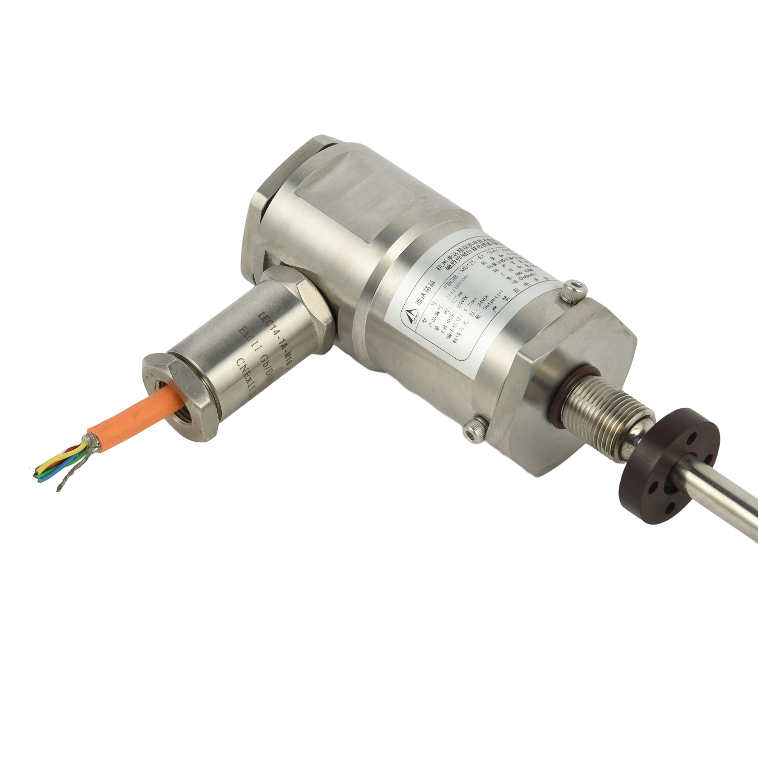
For metallurgy, check the temperature class at the sensor electronics, not just the cylinder surface. Specify heat shielding or remote electronics where needed. Verify resistance to vibration and shock, IP67 or higher sealing, and EMC performance near drives, valves, and power cables. Use stainless or coated housings and robust connectors for washdown and dust. Output type should match the controller: 4-20 mA, SSI, CANopen, or IO-Link. Redundant or safety-rated versions may be required for critical rolling, casting, and forging equipment.
Finally, plan calibration, cable routing, grounding, and maintenance access. Document sensor settings and spare parts to speed up troubleshooting. A properly selected built-in linear displacement sensor improves cylinder positioning accuracy, reduces downtime, and protects production quality in harsh metallurgical environments.
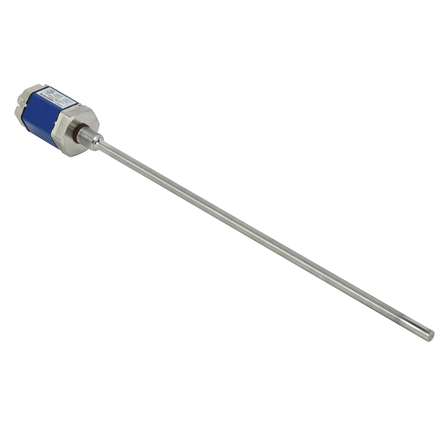 Silo Rod-type Linear Displacem
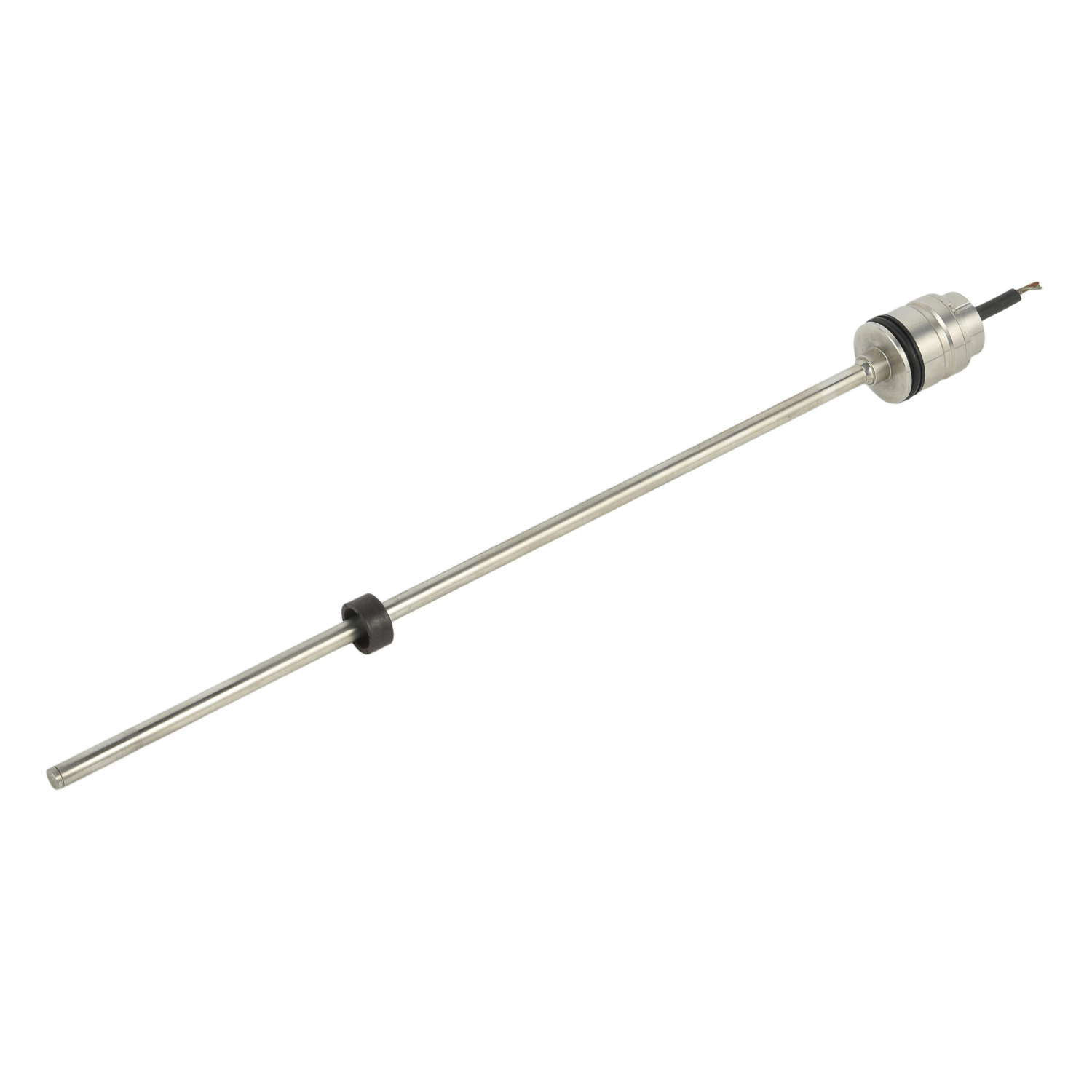 Reaction Kettle Flange-mounted
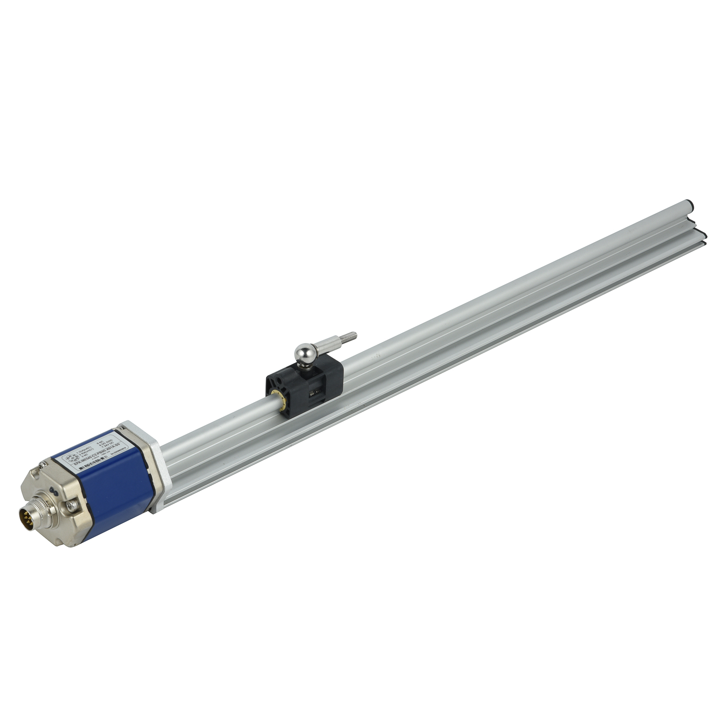 Storage Tank Non-contact Linea
 Material Tank Intrinsically Sa