
WhatNobodyTellsYouAboutMagnetostrictiveLiquidLevelGaugeInstallation
Understanding Magnetostrictive Technology Fundamentals
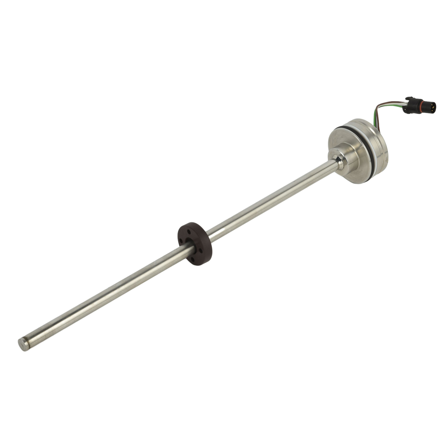
Most installation guides skip the fundamental physics that make these devices work. Magnetostrictive level gauges operate through the interaction between a magnetic float and a waveguide. The float generates a torsional stress wave when it encounters an electrical pulse - this isn't just technical jargon but crucial knowledge for proper installation. Understanding this interaction helps you appreciate why precise alignment matters and why magnetic interference can be devastating to accuracy. The technology's precision stems from measuring the time difference between pulse transmission and wave return, making proper installation not just about mounting but about preserving measurement integrity.
Critical Pre-Installation Considerations Everyone Overlooks
Before you even unbox the gauge, several factors demand attention that most manuals barely mention. Process temperature and pressure ratings seem obvious, but have you considered the specific gravity range of your fluid? The float must be precisely matched to your medium's density, or you'll get permanent measurement errors. Another overlooked aspect: verify your tank's connection flange orientation and ensure sufficient clearance for the probe length. Many installers discover too late that their vessel has internal obstructions that damage the probe during insertion. Always request detailed tank drawings and perform a physical inspection when possible.
The Mounting Process: Beyond Basic Instructions
Standard installation guides provide generic mounting steps, but they miss critical nuances. When installing the flange connection, never use it to pull misaligned pipes into position - this creates permanent mechanical stress on the waveguide. Instead, use proper pipe alignment tools and ensure the flange mates perfectly without force. For top-mounted configurations, verify the probe's free movement before final tightening. The float should slide smoothly along the entire measuring length without binding. Many premature failures occur due to slight bends in the probe caused during installation that aren't visible to the naked eye but create constant friction points.
Wiring Pitfalls That Compromise Accuracy
Electrical connections seem straightforward until you encounter ground loops and signal interference. Use shielded twisted-pair cables exclusively and ground only at the controller end to prevent ground loops. What most don't realize: running level gauge cables alongside motor power lines induces significant measurement drift. Maintain minimum 30cm separation from high-voltage cables and cross them at right angles when unavoidable. For Hart-enabled devices, ensure proper terminating resistance if using multiple devices. These seemingly small wiring details separate functional installations from precision measurement systems that maintain calibration for years.
Calibration Secrets for Long-Term Precision
Field calibration often gets reduced to zero and span adjustment, but mastering trim calibration separates amateurs from experts. Always perform sensor linearity verification at minimum three points across the measuring range, not just at empty and full. This reveals probe issues early. For interface applications, remember that the float's position depends on the density difference between layers, not absolute density. Most calibration errors occur from misunderstanding this principle. After calibration, document the as-left calibration data including temperature conditions - this baseline becomes invaluable for future troubleshooting and performance tracking.
Troubleshooting Common Post-Installation Issues
When measurements drift or become noisy, most technicians immediately blame the sensor. Instead, start by verifying the installation integrity. Check for accumulated debris around the float by comparing upward and downward movement characteristics - differences indicate mechanical obstruction. For erratic readings, measure loop resistance and insulation resistance to identify cable or moisture issues. Surprisingly, 60% of suspected sensor failures stem from installation-related problems like stressed cables or improper grounding. Systematic troubleshooting that revisits installation parameters saves costly sensor replacements and downtime.
Maintenance Practices for Maximum Service Life
Proper installation continues with maintenance practices that preserve initial precision. Establish regular visual inspections for float freedom and probe straightness. For vessels with coating or sediment buildup, schedule cleaning before accumulation affects float movement. Document performance trends to identify gradual degradation before it causes process issues. Remember that the float's magnetic strength diminishes with temperature cycling - factor this into long-term calibration schedules. These maintenance extensions of proper installation principles ensure your magnetostrictive gauge delivers laboratory-grade accuracy in industrial environments for its entire service life.
 YourUltimatePrimeronMagnetostr
TheCoreofInnovation:RecentBrea
DemystifyingLinearity:WhyIt'sC
TheLifecycleStory:Installation
YourUltimatePrimeronMagnetostr
TheCoreofInnovation:RecentBrea
DemystifyingLinearity:WhyIt'sC
TheLifecycleStory:Installation