
HowtoInstallandMaintainMagnetostrictiveDisplacementSensorsforOptimalPerformance
Understanding Magnetostrictive Technology Fundamentals
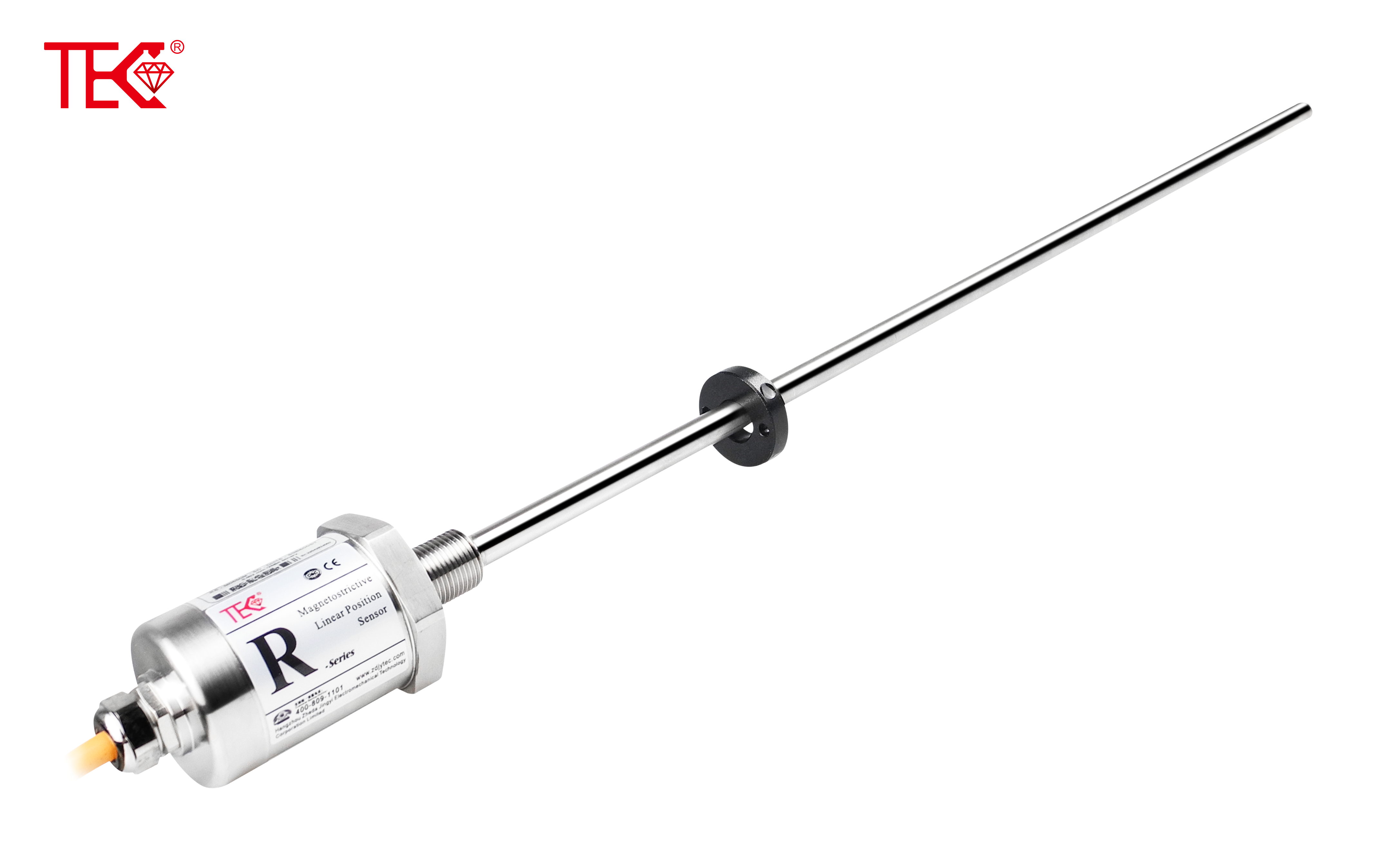
Magnetostrictive displacement sensors operate through the interaction between a magnetic field and ferromagnetic materials. The technology utilizes the magnetostrictive effect where certain materials change their shape when subjected to magnetic fields. A current pulse generates a magnetic field along a waveguide, and when this interacts with a position magnet, it creates torsional stress waves that travel at sonic speed. The time difference between pulse initiation and wave detection provides precise position measurement. This non-contact measurement principle ensures exceptional accuracy and longevity, making these sensors ideal for industrial applications requiring reliable position feedback.
Pre-Installation Planning and Considerations
Proper installation begins with comprehensive planning. Evaluate environmental factors including temperature ranges, potential exposure to chemicals, and electromagnetic interference sources. Verify the sensor's specifications match your application requirements regarding measuring range, output signals, and housing protection class. Ensure the mechanical mounting configuration aligns with the manufacturer's guidelines for alignment tolerances and mounting clearances. Check that the installation location allows adequate space for maintenance activities while protecting the sensor from mechanical damage, vibration, and excessive heat sources.
Mechanical Mounting Best Practices
Secure mounting forms the foundation of sensor performance. Utilize manufacturer-recommended brackets and hardware to ensure stable fixation. Align the sensor parallel to the measurement axis within specified tolerances—typically within 0.5 degrees for optimal accuracy. Avoid imposing mechanical stress on the sensor housing during installation as this can affect measurement precision. For float-level applications, ensure proper guidance and freedom of movement for the float magnet assembly. Implement vibration-damping mounts when installing in high-vibration environments to prevent signal noise and premature component failure.
Electrical Connections and Signal Configuration
Correct electrical integration ensures reliable signal transmission. Follow the manufacturer's wiring diagram precisely, using shielded cables for analog and digital signals to prevent electromagnetic interference. Implement proper grounding techniques by connecting the shield to ground at only one end to avoid ground loops. Configure output signals according to your control system requirements, whether analog voltage/current or digital interfaces like SSI or CANopen. Verify voltage levels and signal scaling before operation. Use conduit seals and cable glands in harsh environments to maintain protection ratings and prevent moisture ingress.
Calibration Procedures for Precision Measurement
System calibration transforms raw signals into accurate position data. Begin with mechanical reference points by positioning the target at known locations. For linear sensors, establish at least two reference points—typically at minimum and maximum stroke positions. Utilize manufacturer-provided software tools for digital calibration and linearization adjustments. Perform temperature compensation calibration if operating across wide temperature ranges. Document calibration parameters and maintain records for future reference. Verify calibration accuracy by checking intermediate points and comparing against precision reference measurements.
Routine Maintenance Protocols
Proactive maintenance ensures long-term reliability and accuracy. Establish regular inspection intervals based on operational hours and environmental conditions. Perform visual inspections for physical damage, corrosion, or contamination accumulation. Check electrical connections for tightness and signs of oxidation. Verify mounting integrity and mechanical alignment during maintenance cycles. Clean sensing elements using appropriate methods without damaging sensitive components. Monitor signal quality trends to detect potential issues before they cause measurement errors or system failures.
Diagnosing Common Performance Issues
Effective troubleshooting requires systematic problem identification. Address signal drift by checking temperature effects and recalibrating if necessary. Resolve signal noise issues by inspecting cable shielding, grounding quality, and electromagnetic interference sources. For complete signal loss, verify power supply voltages, cable continuity, and connector integrity. Mechanical binding or erratic readings may indicate misalignment or damage to the sensing element. Utilize diagnostic tools provided by manufacturers, such as software interfaces that monitor signal quality and system health parameters.
Performance Optimization Techniques
Maximize sensor capabilities through advanced optimization strategies. Implement signal filtering appropriate to your application's dynamic response requirements. Fine-temper response parameters to match your system's mechanical characteristics without introducing overshoot or lag. Utilize available diagnostic functions to monitor performance trends and predict maintenance needs. For critical applications, consider redundant sensor configurations with voting logic for enhanced reliability. Regularly update firmware to access improved features and performance enhancements provided by manufacturers.
Preventive Maintenance Scheduling
Develop comprehensive maintenance schedules based on operational criticality and environmental conditions. Create inspection checklists covering mechanical, electrical, and functional aspects. Establish calibration intervals according to accuracy requirements and operational stability—typically every 6-12 months for precision applications. Maintain spare parts inventory for critical components to minimize downtime. Document all maintenance activities, including measurements before and after service, to track performance trends and identify deteriorating conditions before they affect operations.
Troubleshooting and Failure Analysis
Develop methodical approaches to problem resolution. Begin with symptom analysis and comparison against normal operating parameters. Use process-of-elimination techniques to isolate issues to mechanical, electrical, or control system components. Consult manufacturer documentation for error code interpretations and recommended corrective actions. For persistent or complex issues, utilize specialized diagnostic equipment such as oscilloscopes for signal analysis or precision measurement tools for mechanical verification. Maintain failure records to identify patterns and implement preventive measures for recurring issues.
 YourUltimatePrimeronMagnetostr
TheCoreofInnovation:RecentBrea
DemystifyingLinearity:WhyIt'sC
TheLifecycleStory:Installation
YourUltimatePrimeronMagnetostr
TheCoreofInnovation:RecentBrea
DemystifyingLinearity:WhyIt'sC
TheLifecycleStory:Installation