
MagnetostrictiveLevelGaugeWiringandConnectionDiagram
Understanding the proper wiring and connection of magnetostrictive level gauges is crucial for accurate and reliable level measurement in various industrial applications. These sophisticated instruments provide high-precision continuous level monitoring for liquids in storage tanks, process vessels, and other containers. The correct installation and wiring ensure optimal performance and prevent potential measurement errors that could impact process efficiency and safety.
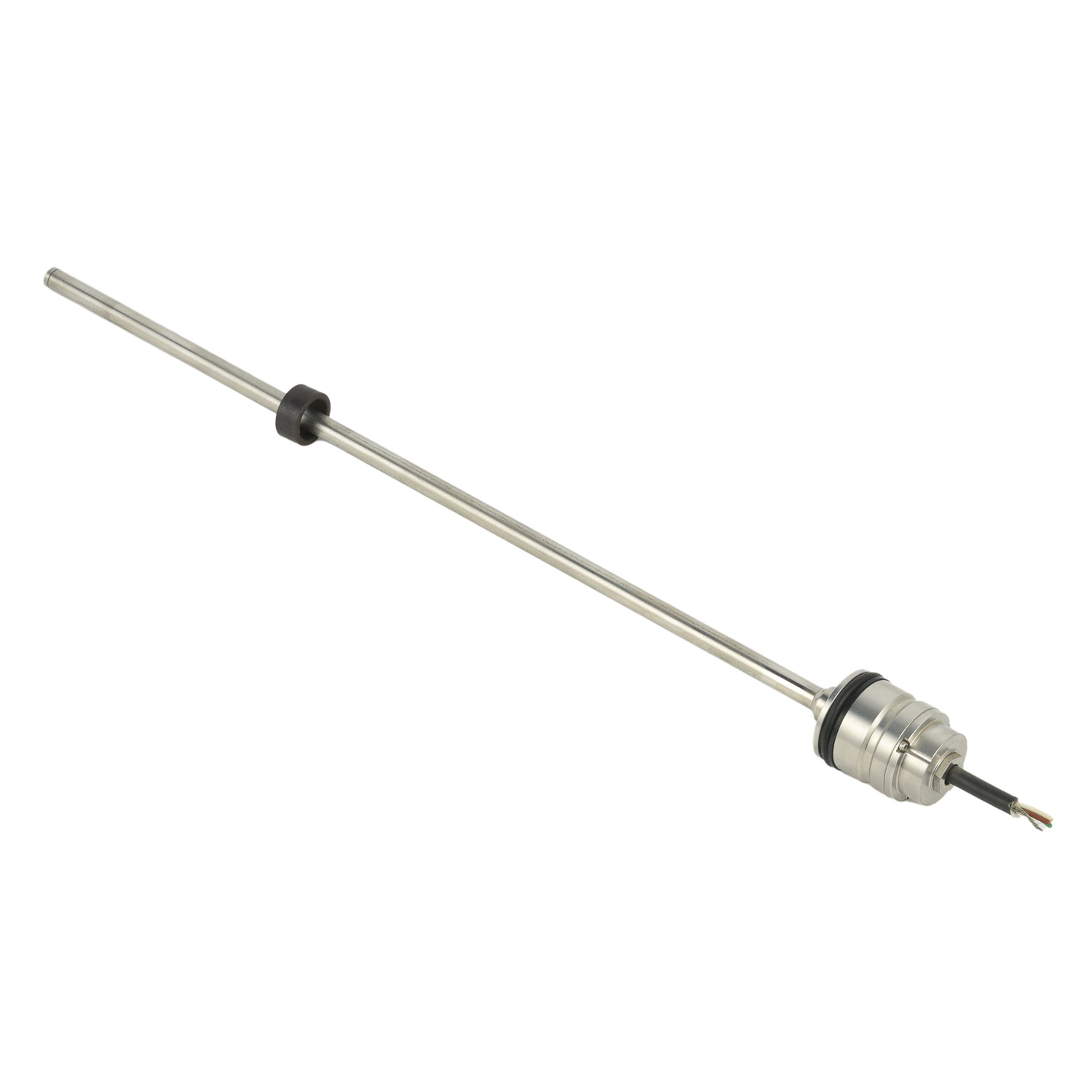
Magnetostrictive Level Transmitter Working Principle
The fundamental operation of magnetostrictive level transmitters relies on the magnetostrictive effect in ferromagnetic materials. A current pulse sent through the waveguide wire generates a circumferential magnetic field along its length. When this field interacts with the axial magnetic field from a permanent magnet float, torsion stress waves propagate along the waveguide in both directions. The electronic head measures the time difference between the transmitted pulse and the returning stress wave to determine the exact float position, which corresponds to the liquid level. This time-of-flight measurement principle delivers exceptional accuracy, typically within ±0.05% of full scale, making it superior to many other level measurement technologies.
Electrical Connection Requirements and Specifications
Proper electrical connections begin with verifying the power supply requirements specified for your magnetostrictive level gauge model. Most industrial transmitters operate on 24 VDC power, though some versions accept wider voltage ranges from 18 to 32 VDC. The current consumption typically falls between 20-40 mA during normal operation. Always consult the manufacturer's datasheet for exact specifications, as improper power supply can lead to measurement inaccuracies or permanent damage to the electronic components. Ensure adequate wire sizing based on the distance from the power source, with 18-22 AWG shielded cable generally recommended for most installations to minimize voltage drop and electrical interference.
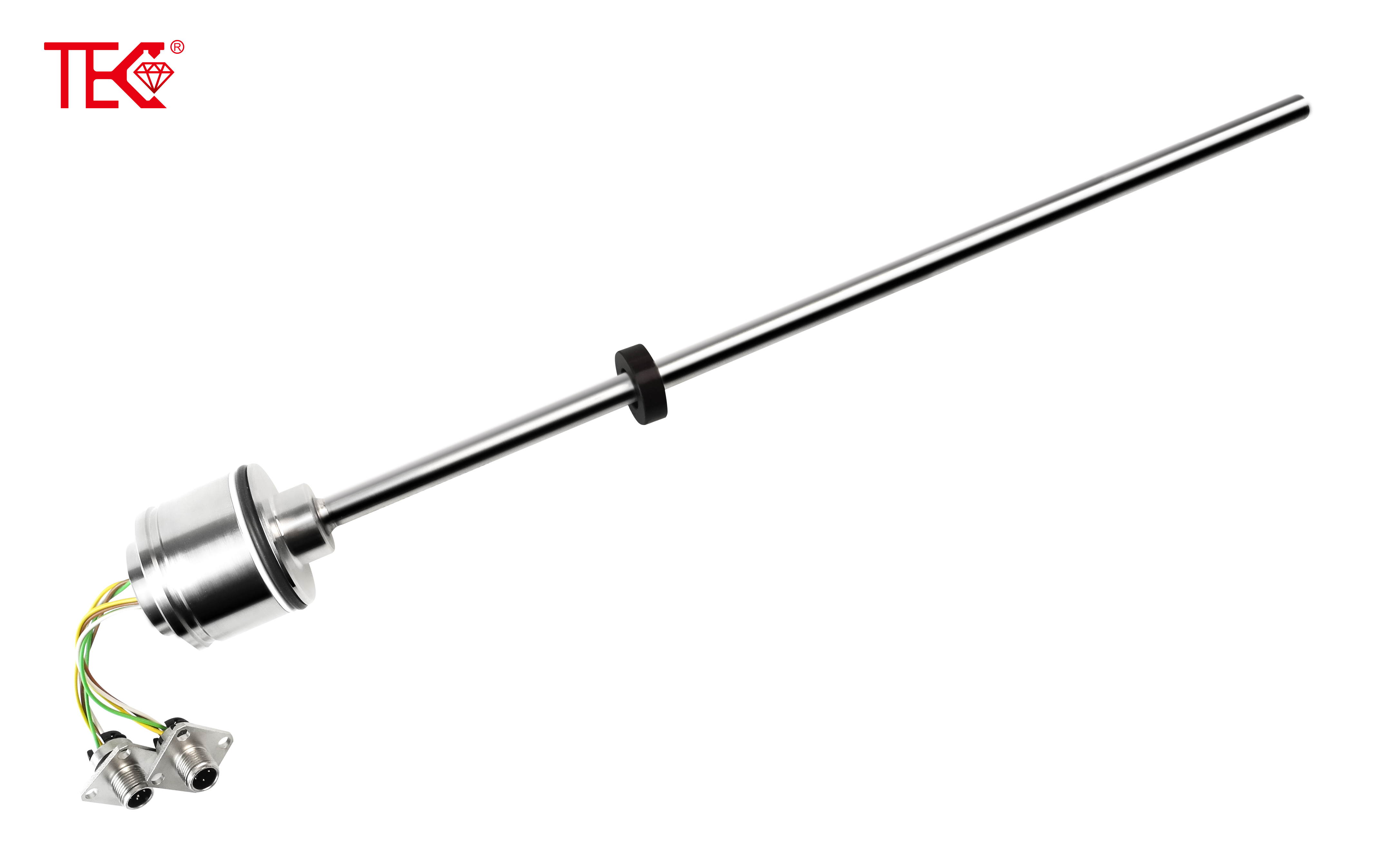
Wiring Diagram Interpretation and Components
A standard magnetostrictive level gauge wiring diagram illustrates the connections between the transmitter, power supply, and output signal receivers. The diagram typically shows a four-wire configuration: two wires for power supply (positive and negative) and two wires for the output signal. For 4-20 mA analog output models, the signal wires connect to the appropriate input channels of your PLC, DCS, or indicator. HART-enabled transmitters include additional communication lines for digital signal transmission alongside the analog output. Some advanced models feature Foundation Fieldbus or PROFIBUS PA digital interfaces, requiring specialized connection protocols and cabling arrangements as specified in the wiring schematic.
Power Supply Connection Procedures
Connecting the power supply requires careful attention to polarity and grounding practices. Begin by routing the power cables through appropriate conduit entries and securing them with cable glands to maintain environmental protection. Connect the positive DC wire to the terminal marked "+V" or "Power+" and the negative wire to the terminal marked "-V" or "Power-". Implement proper grounding by connecting the shield drain wire to the designated ground terminal, typically located separately from the power terminals. This grounding practice is essential for minimizing electrical noise interference that could compromise measurement accuracy. Install surge protection devices if the transmitter is located in areas prone to lightning strikes or power surges.
Signal Output Wiring Configuration
The signal output wiring configuration depends on your specific control system requirements. For standard 4-20 mA analog output, connect the positive signal wire to the "+OUT" or "Signal+" terminal and the negative wire to the "-OUT" or "Signal-" terminal. When implementing HART communication, ensure the HART modem or communicator connects across the 250-ohm load resistor in the current loop. For RS-485 Modbus output configurations, carefully connect the Data+ (A), Data- (B), and common ground wires according to the terminal designations. Maintain proper wire separation between power and signal cables, with a minimum distance of 6 inches recommended to prevent capacitive coupling and signal distortion.
Installation Best Practices and Safety Considerations
Proper installation begins with selecting an appropriate location that avoids areas of high turbulence, direct inlet streams, or mechanical vibration. Ensure the gauge is mounted vertically according to the manufacturer's specified tolerances, typically within 1-3 degrees of true vertical. Implement electrical safety measures by disconnecting power before performing any wiring work and using appropriate personal protective equipment. Install lightning arrestors and surge protectors for outdoor applications, particularly in geographic regions with frequent electrical storms. Verify that all conduit entries are properly sealed to prevent moisture ingress, which can cause corrosion and electrical shorts over time.
Troubleshooting Common Wiring Issues
Common wiring issues with magnetostrictive level gauges often manifest as erratic readings, signal dropout, or complete communication failure. Begin troubleshooting by verifying power supply voltage at the transmitter terminals with a multimeter, ensuring it falls within the specified operating range. Check for loose connections, corroded terminals, or damaged wires that could interrupt signal transmission. Measure the output current loop with the process fluid at known levels to verify the 4-20 mA signal corresponds correctly to the measured level. For communication problems with smart transmitters, verify the HART network configuration, including proper load resistance and network isolation. Always consult the manufacturer's troubleshooting guide for specific error codes and diagnostic procedures.
 YourUltimatePrimeronMagnetostr
TheCoreofInnovation:RecentBrea
DemystifyingLinearity:WhyIt'sC
TheLifecycleStory:Installation
YourUltimatePrimeronMagnetostr
TheCoreofInnovation:RecentBrea
DemystifyingLinearity:WhyIt'sC
TheLifecycleStory:Installation