How to prevent signal attenuation in magnetostrictive sensors?
Understanding Signal Attenuation in Magnetostrictive Sensors
Signal attenuation in magnetostrictive sensors occurs when the electrical signal weakens as it travels through the sensing system, resulting in measurement inaccuracies and reduced performance. This phenomenon typically stems from impedance mismatches, cable quality issues, electromagnetic interference, or improper installation practices. The magnetostrictive effect itself relies on precise timing measurements between torsional strain waves and electrical pulses, making signal integrity paramount. Recognizing early signs of attenuation, such as drifting readings or decreased resolution, enables proactive maintenance before critical failures occur.
Proper Cable Selection and Installation Techniques
Selecting appropriate coaxial cables with proper impedance matching (typically 50 or 75 ohms) significantly reduces signal loss. High-quality shielded cables with low capacitance per unit length minimize amplitude reduction over distance. Maintain cable integrity by avoiding sharp bends, crushing, or exposure to extreme temperatures that alter electrical characteristics. Implement strain relief at connection points to prevent internal wire damage that causes impedance discontinuities. For long-distance transmissions, consider using signal amplifiers or repeaters at strategic intervals to maintain signal strength without compromising accuracy.
Shielding Against Electromagnetic Interference
Electromagnetic interference (EMI) from motors, power lines, or radio frequency sources induces noise that attenuates sensor signals. Employ multilayer shielding using both braided and foil shields in cables for comprehensive protection. Proper grounding techniques establish a reference point that diverts interference away from signal paths. Install sensors away from high-emission sources when possible, and use grounded metal conduits for cable routing in electrically noisy environments. Ferrite beads installed near connection points suppress high-frequency noise that contributes to signal degradation.
Regular Maintenance and Calibration Procedures
Establish periodic inspection routines checking for cable abrasions, connector corrosion, and shield integrity. Clean electrical contacts using appropriate solvents to maintain optimal conductivity. Perform baseline calibration using certified reference points to detect early attenuation trends. Monitor power supply stability since voltage fluctuations directly impact signal strength. Maintain environmental controls as temperature variations affect both mechanical and electrical components. Document maintenance activities to identify patterns and predict future attenuation issues before they affect measurement accuracy.
Troubleshooting Common Attenuation Issues
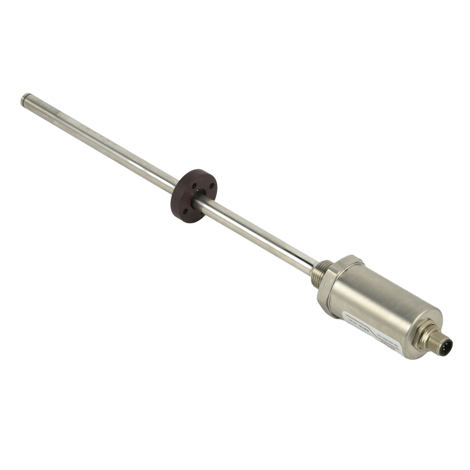
When attenuation occurs, systematically test cable segments using time-domain reflectometry to locate faults. Verify termination resistances match system impedance requirements. Check all connections for tightness and corrosion that increase resistance. Use spectrum analyzers to identify specific frequency interference issues. Implement differential signaling techniques where possible to cancel noise-induced attenuation. For persistent problems, consider upgrading to industrial-grade components specifically designed for high-noise environments. Consult manufacturer guidelines for environment-specific solutions that address unique attenuation challenges in your application.
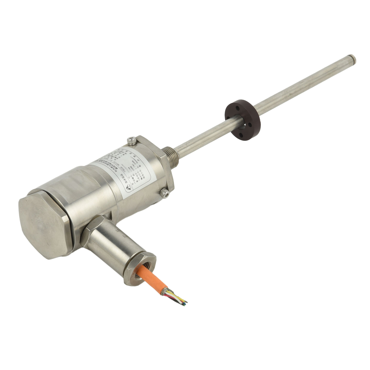 UpgradingYourLevelMeasurementS
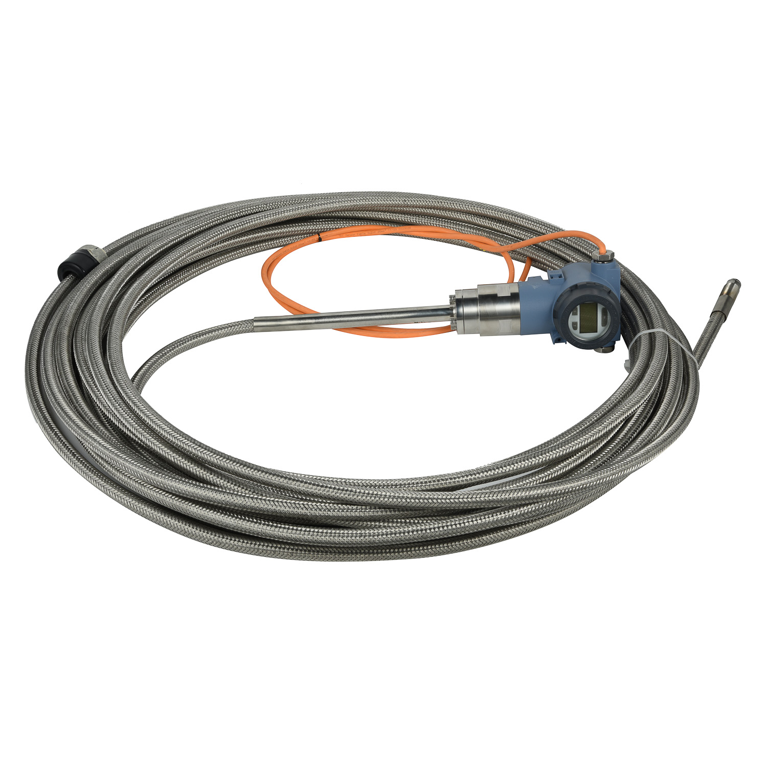 Why are magnetostrictive level
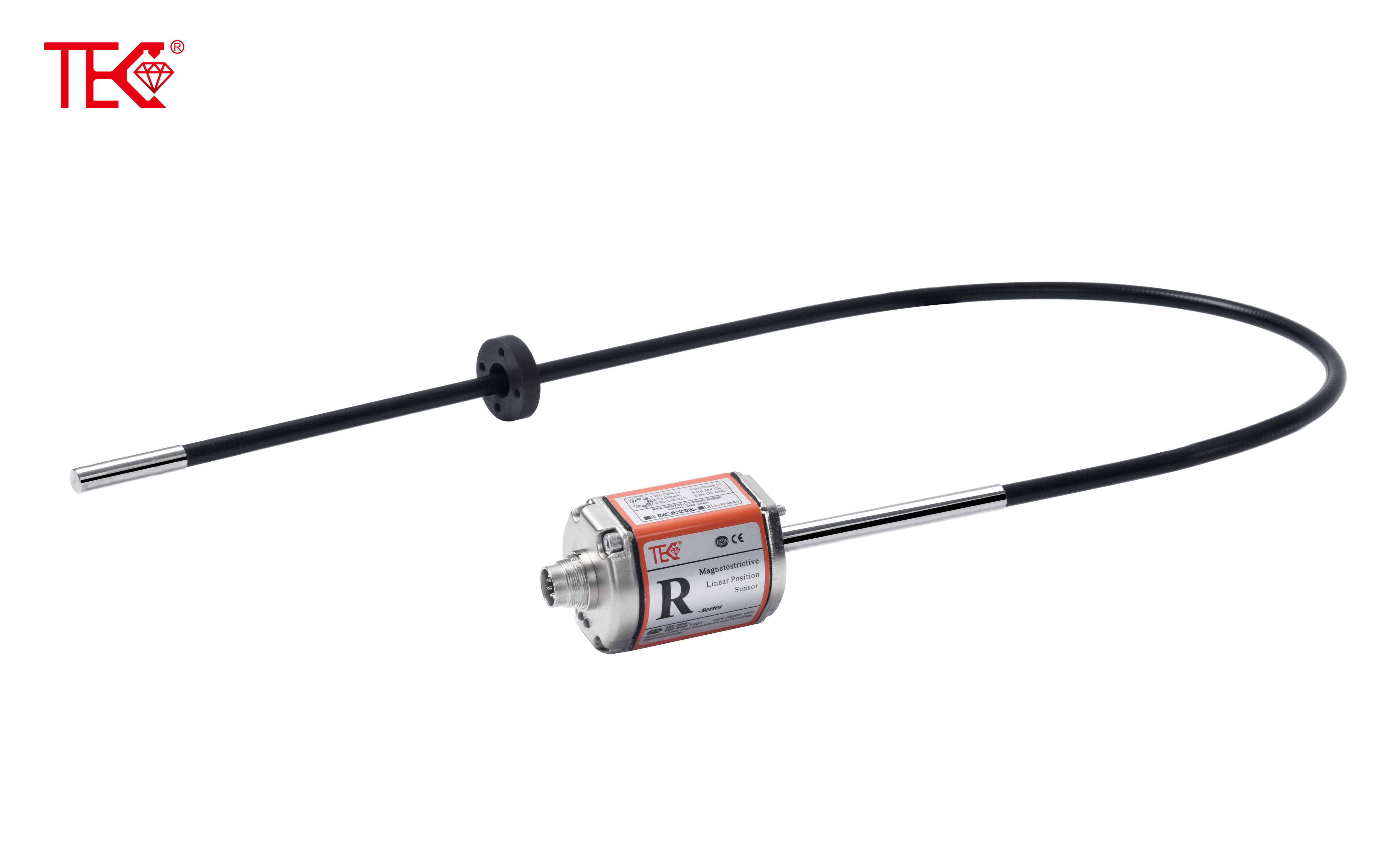 ComparingMagnetostrictiveandRa
 MagnetostrictiveLevelSensorfor
