
How to connect magnetostrictive sensors to PLC systems?
Understanding Magnetostrictive Sensor Technology
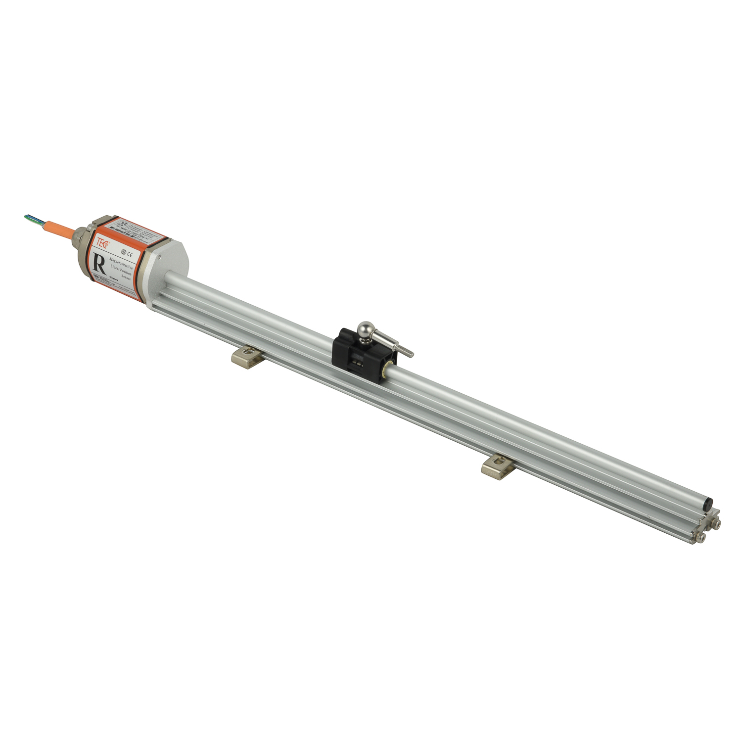
Magnetostrictive sensors operate using the magnetostriction principle where a magnetic field interacts with a ferromagnetic waveguide to generate precise position measurements. These sensors consist of three main components: a position magnet that moves along the sensing rod, an electronic transducer head, and a waveguide that transmits torsional waves. The technology delivers exceptional accuracy in harsh industrial environments, making it ideal for hydraulic cylinder positioning, valve control, and material handling applications where reliability is paramount.
Pre-Connection Planning and Requirements
Before initiating physical connections, verify your PLC's input specifications match the magnetostrictive sensor's output signals. Most modern magnetostrictive sensors provide analog outputs (4-20mA or 0-10V) or digital interfaces (SSI, CANopen, Profibus). Ensure you have the appropriate interface module installed in your PLC rack, such as an analog input card for current/voltage signals or a dedicated communication module for bus protocols. Check power requirements - typically 10-30V DC - and ensure your power supply can deliver clean, stable voltage to prevent signal interference.
Wiring Configuration and Electrical Connections
Begin by routing shielded cable between the sensor and PLC, maintaining separation from power cables to minimize electromagnetic interference. Connect the power leads to your DC supply, ensuring proper polarity protection. For analog outputs, wire the 4-20mA or 0-10V signals to the designated analog input channels on your PLC module, making sure to establish a common ground reference. For digital interfaces like SSI, connect clock and data lines according to the protocol specification, using twisted-pair cables with proper termination resistors when required.
PLC Configuration and Parameter Setting
Access your PLC programming software to configure the input module parameters. For analog signals, set the appropriate scaling values to convert raw input data to engineering units (millimeters or inches). Calibrate the zero and span points corresponding to your sensor's measurement range. For digital interfaces, configure the communication parameters to match the sensor's protocol settings including baud rate, data bits, and parity. Establish the measurement update rate considering both your application requirements and the sensor's maximum response frequency.
Testing and Troubleshooting Procedures
After completing connections, power up the system and observe the sensor's status indicators. Use the PLC programming software to monitor the input values while moving the target magnet through its full range. Verify the readings correspond to actual positions and check for signal dropouts or noise. If encountering issues, use a multimeter to check power supply stability, measure output signals directly at the sensor connector, and inspect grounding quality. Common problems include incorrect scaling, electromagnetic interference, or cable integrity issues that require systematic diagnosis.
 YourUltimatePrimeronMagnetostr
TheCoreofInnovation:RecentBrea
DemystifyingLinearity:WhyIt'sC
TheLifecycleStory:Installation
YourUltimatePrimeronMagnetostr
TheCoreofInnovation:RecentBrea
DemystifyingLinearity:WhyIt'sC
TheLifecycleStory:Installation